FT-897D Data Interface Circuit
Data modes really interest me, especially PSK31. When I got my FT-897D I surveyed all the options for how to connect my radio to my PC. Upon purchase, I got the RT Systems CAT cable (USB-62), but that only provided remote control and programming. My options at this point were to purchase a SignaLink, RigBlaster or the like OR build something myself. What I had read seemed to indicate the FT-897’s “Data Port” was simply a way for the audio to get to the computer w/o being affected by volume or the headphones or speaker plugged in. I was using the speaker output, but when the headphones were plugged in they muted it. It was also affected by changing the volume. There was also no way to input the audio to reply using my computer.
Most of what I read online said that you could take an old PS/2 cable, like an extension, and splice on some audio connectors. One for the data into the radio and one for the data out of the radio. This works, however is not as optimal as another solution. The next solution is just a variation on the first one, but isolates both the radio and the computer from each other using some 1:1 audio transformers.
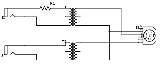
Here is a sample circuit:
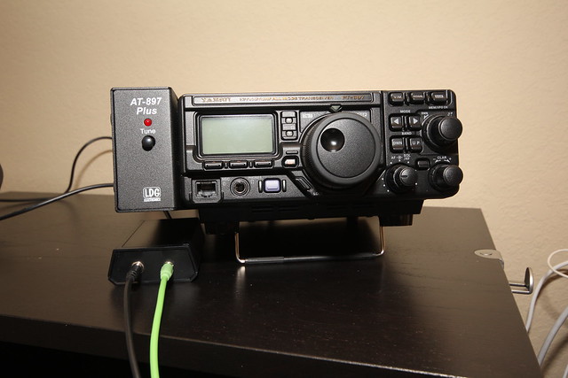
This can be enclosed in a project box, which makes it look real slick.
Supplies:
- 2 x 1:1 audio transformers. I used a 600Ω:600Ω one from a local supply store. $3 ea
- 2 x 3.5mm audio jacks $1.50/ea
- 1 x perf board $4
- 1 x project box (good if the perf board fits in project box!) $6
- 1 x PS/2 extension cable *i got mine free, but usually $5-6 on amazon”
- 1 x 10kΩ or 1kΩ resistor. could use a pot instead to adjust the output volume. pack of 5 $1
J1 and J2 are the audio jacks, R1 is a 10kΩ resistor, T1 and T2 are the transformers. J3 is the PS/2 cable.
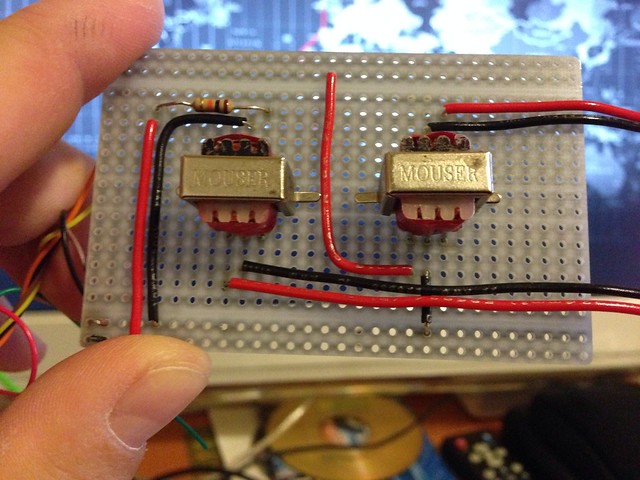
Here is what my finished circuit looked like:
and the finished product in the project box:
Notes:
First, the Data connector diagram on the radio is the connector on the radio. You have to diagram the reverse for the cable. Then you need to figure out which wire goes to which pin on the cable connector.
Second, on my cable, the connector was U shaped and the top flat part had to be shaved down to fit in the hole in the back of the radio.
Third, instead of tying a knot in the cord inside the project box, I just put a zip tie real snug around it and snipped the end of. helped with the bulk inside the box.
Fourth, you can find project box/board combos. also, you don’t even need to do all this and can just hook the wires right to audio connectors. the resistor might be necessary as the output volume from your computer can be quite high.
Fifth, this doesn’t control the radio. You still need a control cable. I used the DigiVox feature on the radio, but the control cable can PTT or you can find plans to use the PTT lead on the Data cable as well. Dropping that one low triggers PTT. Use the Data Out 1200 baud line, not the 9600 one.
“Data Out” means out of the radio, Data In means data into the radio. I labeled the plugs on the interface with “To Comp” and “From Comp”. Also used an external soundcard (iMic) so I didn’t have to muck with my regular audio settings. This whole setup works fantastic with HRD and FLDigi, on a Mac or with Windows.
LMK if you have questions.
Data modes really interest me, especially PSK31. When I got my FT-897D I surveyed all the options for how to connect my radio to my PC. Upon purchase, I got the RT Systems CAT cable (USB-62), but that only provided remote control and programming. My options at this point were to purchase a SignaLink, RigBlaster or the like OR build something myself. What I had read seemed to indicate the FT-897’s “Data Port” was simply a way for the audio to get to the computer w/o being affected by volume or the headphones or speaker plugged in. I was using the speaker output, but when the headphones were plugged in they muted it. It was also affected by changing the volume. There was also no way to input the audio to reply using my computer.
Most of what I read online said that you could take an old PS/2 cable, like an extension, and splice on some audio connectors. One for the data into the radio and one for the data out of the radio. This works, however is not as optimal as another solution. The next solution is just a variation on the first one, but isolates both the radio and the computer from each other using some 1:1 audio transformers.
Here is a sample circuit:
This can be enclosed in a project box, which makes it look real slick.
Supplies:
- 2 x 1:1 audio transformers. I used a 600Ω:600Ω one from a local supply store. $3 ea
- 2 x 3.5mm audio jacks $1.50/ea
- 1 x perf board $4
- 1 x project box (good if the perf board fits in project box!) $6
- 1 x PS/2 extension cable *i got mine free, but usually $5-6 on amazon”
- 1 x 10kΩ or 1kΩ resistor. could use a pot instead to adjust the output volume. pack of 5 $1
J1 and J2 are the audio jacks, R1 is a 10kΩ resistor, T1 and T2 are the transformers. J3 is the PS/2 cable.
Here is what my finished circuit looked like:
and the finished product in the project box:
Notes:
First, the Data connector diagram on the radio is the connector on the radio. You have to diagram the reverse for the cable. Then you need to figure out which wire goes to which pin on the cable connector.
Second, on my cable, the connector was U shaped and the top flat part had to be shaved down to fit in the hole in the back of the radio.
Third, instead of tying a knot in the cord inside the project box, I just put a zip tie real snug around it and snipped the end of. helped with the bulk inside the box.
Fourth, you can find project box/board combos. also, you don’t even need to do all this and can just hook the wires right to audio connectors. the resistor might be necessary as the output volume from your computer can be quite high.
Fifth, this doesn’t control the radio. You still need a control cable. I used the DigiVox feature on the radio, but the control cable can PTT or you can find plans to use the PTT lead on the Data cable as well. Dropping that one low triggers PTT. Use the Data Out 1200 baud line, not the 9600 one.
“Data Out” means out of the radio, Data In means data into the radio. I labeled the plugs on the interface with “To Comp” and “From Comp”. Also used an external soundcard (iMic) so I didn’t have to muck with my regular audio settings. This whole setup works fantastic with HRD and FLDigi, on a Mac or with Windows.
LMK if you have questions.